How to Design for 3D Printing: Our Complete Handbook
Edition 115 min read
How thick should a wall be? What will print without supports? And how big do holes, gaps and lettering need to be so the part comes out right the first time?
This handbook answers those questions with the numbers we print to every day. Each section is short, so read it front to back or jump straight to the rule you need.
Want it as a PDF? Download the free handbook (PDF, 1.1 MB) to keep beside your CAD software.
Contents
- How your part gets made
- Walls and thin features
- Overhangs and bridges
- Corners, edges and warping
- Holes, pins and fits
- Splitting large parts
- Orientation and strength
- Text, detail and color
- Picking a material
- Designing with AI
- Sending us your file
1. How your part gets made
A nozzle draws one thin line of melted plastic at a time, one layer on top of the last. Nearly every rule in this handbook follows from that: lines have a width, layers have a height, and every layer needs something underneath it.
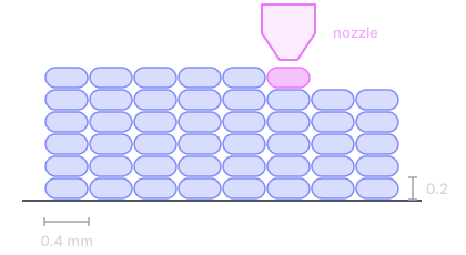
Lines. Each pass of the nozzle lays a line about as wide as the nozzle opening.
Layers. Lines are stacked in thin layers, so curves and slopes are built as tiny steps.
Support. A new layer can only reach a little past the one below it before it droops.
Three numbers come up again and again:
| Number | What it means |
|---|---|
| 0.4 mm | Line width. Walls come in multiples of this. Need a different line width? We also run 0.2, 0.6 and 0.8 mm on demand. |
| 0.2 mm | Typical layer height, and the smallest step in Z. Specify 0.12 mm or 0.16 mm for higher resolution. |
| 45° | The flattest overhang that prints clean without support. |
2. Walls and thin features
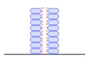
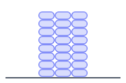
Make walls at least 0.8 mm thick, ideally 1.2 mm or more, in steps of 0.4 mm. A wall is really a number of lines side by side, and the slicer can only fit whole lines.
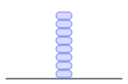
0.4 mm, one line: avoid. Fragile, wobbles as it grows, and may be dropped by the slicer.
1.0 mm, two lines and a gap: avoid. There's no room for a third line, so a seam or void runs up the middle.
1.2 mm, three lines: prints well. Solid, stiff and clean. A good default for most walls.
Pins and posts
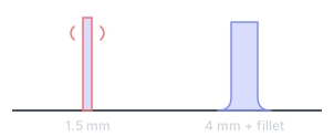
Thin, tall features wobble as the nozzle passes and snap easily. Keep pins 3 mm or thicker, and add a fillet where they meet the part.
| Rule | Value |
|---|---|
| Minimum wall | 0.8 mm |
| Recommended wall | 1.2 to 1.6 mm |
| Load-bearing wall | 2.0 mm or more |
| Wall step | 0.4 mm |
| Minimum pin diameter | 3 mm |
Thicker is not always stronger. Past about 2.4 mm, extra wall mostly adds weight and cost. If you need a stiffer part, tell us and we'll adjust walls and infill in the slicer, rather than you modeling it solid.
3. Overhangs and bridges
Slopes up to 45° from vertical print clean. Anything flatter needs support material, which we remove by hand and which leaves a rougher surface wherever it touched.
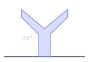
Gentle slopes: prints well. Each layer steps out a little. At 45° or steeper, no support is needed.
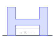
Short bridges: prints well. A flat span between two supports is fine up to about 10 mm. Longer spans sag.
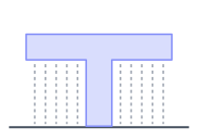
Flat overhangs: needs support. There's nothing to build on, so the slicer adds supports, and those marks show.
Chamfer bottom edges, don't round them
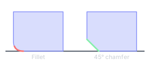
A fillet on a downward-facing edge begins as a flat overhang and droops. A 45° chamfer prints clean. Fillets on top edges are fine.
| Rule | Value |
|---|---|
| Unsupported overhang | 45° from vertical |
| Unsupported bridge | up to 10 mm |
| Bottom-edge chamfer | 45° |
| First-layer edge chamfer | 0.5 mm |
The first layer is pressed down and spreads slightly. A small chamfer on the bottom edge hides it.
Try rotating before you add supports. Many parts that look like they need support don't once they're turned over. If one face has to look good, tell us and we'll orient the part to keep supports off it.
4. Corners, edges and warping
Plastic shrinks as it cools, and sharp corners are where that pull concentrates. Round the corners and break the edges, and the part stays flat on the bed.
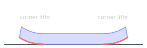
Sharp, square footprint: avoid. Cooling pulls hardest at sharp corners, so they peel off the bed mid-print.
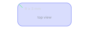
Rounded vertical corners: prints well. A radius spreads the pull around the corner, so the footprint stays down.
Chamfer the bottom, round the top
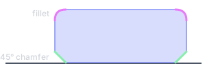
A chamfer on the bottom edge hides first-layer squish and needs no support. Fillets suit top edges, where they print clean.
| Rule | Value |
|---|---|
| Vertical corner radius | 3 mm or more |
| Corner radius, parts over 100 mm | 5 mm or more |
| Bottom-edge chamfer | 0.5 to 1 mm at 45° |
| Inside corner fillet | 1 mm or more |
Big, flat and thin is the hardest shape to print. ASA warps more than PLA or PETG. Round sharp inside corners too, since cracks start there. Tell us about large flat parts and we'll add a brim if one is needed. It trims off but can leave a slight edge.
5. Holes, pins and fits
Holes print slightly small and pegs slightly big, because each line spreads a little as it's laid. Model holes 0.2 mm larger than nominal, and leave a gap between parts that fit together.
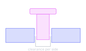
| Fit | Clearance per side |
|---|---|
| Press fit: pushes in hard, stays put | 0.1 mm |
| Sliding fit: moves with light friction | 0.2 mm |
| Free fit: turns or slides freely | 0.3 to 0.4 mm |
| Print-in-place: hinges printed assembled | 0.4 to 0.5 mm |
Sideways holes: use a teardrop
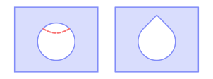
The top of a round hole printed on its side is a flat overhang, so it sags. A pointed 45° top, as a teardrop or diamond, prints clean.
| Rule | Value |
|---|---|
| Minimum hole | 2 mm |
| Hole oversize | +0.2 mm |
| Gap between separate parts | 0.5 mm or more |
| Typical accuracy | ±0.2 mm |
| Teardrop point angle | 45° |
Fit values are a starting point for PLA and PETG. TPU needs more room.
Precise bores: add 0.2 mm, then check. For bearings and dowels, model the hole 0.2 mm over nominal and finish it with a reamer if the fit must be exact. If a fit really matters, ask us before you order.
6. Splitting large parts
If a part is bigger than our build plate, or would print better in pieces, split it. We offer three ways to put the pieces back together: dovetails, dowel pins and heat-set inserts.
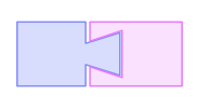
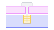
Dovetail. The halves slide together and line themselves up. No hardware, and easy to glue for a permanent joint. Best for panels, signs, props and long flat parts.
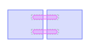
Dowel pins. Pins sit in matching holes on both halves for precise alignment, pressed in or glued. Best for enclosures, models and parts with a visible seam.
Heat-set inserts. We melt threaded brass inserts into one half, so the parts bolt together and come apart again. Best for parts you'll open for service or ship flat.
Where to split
- On a flat face, so each half has a clean side to sit on the bed.
- Away from show faces, where a seam would be seen.
- Away from high-load areas, since the joint is the weakest point.
- Where it cuts supports, so each piece prints cleanly on its own.
| Rule | Value |
|---|---|
| Dovetail clearance per side | 0.2 mm |
| Dowel hole, press fit | pin + 0.2 mm |
| Dowel hole, glued | pin + 0.4 mm |
| Dowels per joint | 2 or more |
| Wall around an insert | 2 mm or more |
Not sure where to split? Send us the whole model and the size you need. We'll suggest where to split it and which joint to use before you pay. There's more on this in Too Big to Print? We'll Cut It Up.
7. Orientation and strength
A printed part is strongest along its layers and weakest between them. Orient it so the load runs along the lines, not across the joins between layers.
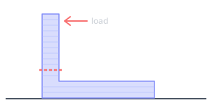
Printed standing up: avoid. Layers stack across the upright arm. A push on the top peels them apart at the corner.
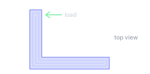
Printed lying on its side: prints well. Lines run the full length of both arms and round the corner. Same part, many times tougher.
How each face will look
- Top faces are the smoothest, with a fine line pattern.
- The bottom face is flat and takes the texture of the build plate.
- Side walls show fine horizontal layer lines.
- Shallow slopes show visible steps. Steeper reads smoother.
- Supported faces are rougher wherever support touched.
- Round holes come out roundest when they point straight up.
Tell us which way is up. Strength, looks and support all pull on orientation, and sometimes they disagree. If one face has to look good or one direction takes the load, say so when you order.
8. Text, detail and color
Raised and engraved text both print well if the strokes are thick enough. Keep letters at least 10 mm tall so they read clearly. Bold sans-serif fonts survive; hairline serifs don't. To make text stand out, color often works better than depth.
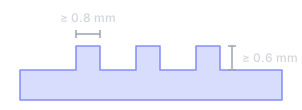
Embossed (raised). Strokes at least 0.8 mm wide, standing at least 0.6 mm proud. Best on top faces.
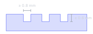
Engraved (cut in). Strokes at least 0.8 mm wide, cut at least 0.6 mm deep. Reads well on side walls.
Multicolor: up to 13 colors in one print
Send a 3MF with colors painted or assigned per part. Bambu Studio and OrcaSlicer both save this. Tell us which filament each color should be.
Every color change adds print time, so a few colors over large areas cost less than many colors in small spots. Our multicolor guide goes into more detail.
| Rule | Value |
|---|---|
| Text stroke width | 0.8 mm or more |
| Raise or depth | 0.6 mm or more |
| Letter height | 10 mm or more |
| Smallest detail, X and Y | 0.4 mm |
| Smallest detail, Z | 0.2 mm |
Details smaller than a line don't print. The slicer drops or merges anything under about 0.4 mm. If a logo or label is tiny, scale it up or let color carry it instead of relief.
9. Picking a material
Most parts fit one of these. Choose by where the part will live and what it has to survive, then design to that material's limits.
| Material | Good for | Watch for |
|---|---|---|
| PLA: rigid, crisp detail | Display pieces, prototypes, indoor enclosures. Widest color range. | Heat. It softens around 55 °C, so not for a hot car or near a heater. |
| PETG: tough, a little flex | Functional parts, clips, brackets, light outdoor use. | Fine detail and bridges, which come out a little softer than in PLA. |
| PCTG: impact resistant, clearer | Parts that get dropped or knocked, snap fits, translucent parts. | The same heat limits as PETG. It isn't a high-temperature material. |
| ASA: built for outdoors | Parts that live in sun and weather, or near heat: garden, vehicle and exterior fittings. | Warping on large, flat parts. Round sharp corners and avoid long thin slabs. |
| TPU and PEBA: soft and flexible | Gaskets, bumpers, grips and feet. PEBA is lighter and springier than TPU. PEBA is coming soon. | Bridges and thin overhangs. Keep walls 1.2 mm or more and fits loose. |
| Engineering grade: fiber blends, nylon, PC | Stiffness, higher heat or chemical exposure. Tell us the load and environment and we'll recommend one, and what it costs, before you pay. | Brittleness across layers. Add fillets and loosen fits. |
Solid infill: rarely necessary, and rarely stronger. Wall count and orientation usually matter more than how full the inside is. Ask us before you pay for solid. Our infill guide explains why, and Choosing a Material covers each material in more depth.
10. Designing with AI
ChatGPT and Claude don't sculpt. They write code that builds the shape. Describe the part like an engineer, ask for the right file, and check it before you send it.
Put in the prompt:
- What it does, in a sentence.
- Every key dimension, in millimeters.
- What it fits onto, and how tight.
- Hardware by name: screws, magnets.
- Load, heat and which face sits down.
Ask for back:
- STL for single-color parts.
- 3MF for multicolor (see below).
- The source code, for later changes.
- Millimeters, asked for by name.
- Proof of a mesh check, not a claim.
Paste into every prompt
Design for FDM printing with a 0.4 mm nozzle:
- Minimum wall thickness 1.2 mm; no feature thinner than 0.8 mm.
- Keep overhangs at 45 degrees or less from vertical where possible.
- Put a 0.5 mm chamfer on bottom edges instead of a fillet.
- Make holes 0.2 mm larger than the nominal size.
- Clearance between parts that must fit together: 0.2 mm for snug, 0.4 mm for loose.
- Raised or recessed text at least 0.6 mm deep and 10 mm tall.
- The model must be a single watertight solid with no internal faces.
Multicolor: ask for a Bambu Studio painted 3MF
Each triangle carries a paint_color code naming a filament slot, in uppercase, up to AC for slot 13. Open the file in Bambu Studio, set each slot's color, then choose File > Save Project and upload that file, so our quote form can price every color.
| Slot | 1 | 2 | 3 | 4 | 5 | 6 | 7 | 8 |
|---|---|---|---|---|---|---|---|---|
paint_color |
4 |
8 |
0C |
1C |
2C |
3C |
4C |
5C |
The full walkthrough, with example prompts and a downloadable sample file, is in How to Use ChatGPT and Claude to Make 3D Printable Models.
11. Sending us your file
A clean file and a few lines of context get you the right part the first time. Run through this before you upload.
File checklist
- STL or 3MF. Use 3MF if you've assigned colors.
- Millimeters. Check the size on export; inches turn a 50 mm part into a 2 mm one.
- Watertight. No holes in the mesh, no zero-thickness faces.
- Smooth enough. Enough triangles that curves aren't faceted, not millions.
- One part per file, or tell us how the parts go together.
- Clear file names, so we can match them to your notes.
What to tell us
Upload your model and we'll price it from a real slice of your part, not an estimate. Most orders are printed and shipped within 2-3 days. When you order, tell us:
- What it's for, in a sentence.
- What it fits with, and the size of that thing.
- Which faces are seen, so we keep supports off them.
- Which way the load goes, so we orient for strength.
- Where it will live: indoors, outdoors, in a car, near heat.
- How many you need, now and later.
Not sure your design will print? Ask us first.